Reading a Simple Woodworking Plan Before You Begin
Connect a woodworking plan’s views, dimensions, stock list, and assembly order before cutting parts for a shelf or another wooden project.
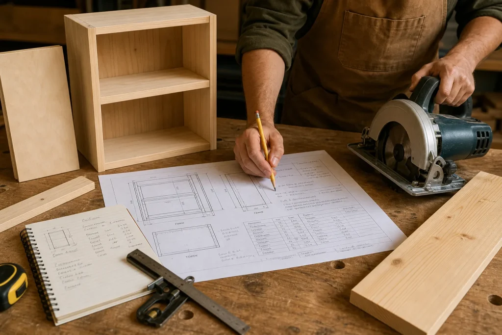
A beginner sets a shelf plan beside a pine board and reaches for a circular saw. The front view shows two sides, a top, and a bottom, but says little about the shelf’s depth; the materials list includes a back panel that is hard to make out in the sketch. A pause to resolve those details can prevent a pile of accurately cut parts from failing to fit.
The following shelf scenario is invented and hypothetical. Its lesson is practical: read a plan as a connected set of views, dimensions, materials, and operations. Identify which details control fit, check that the listed stock can supply the parts, and settle unclear joints before cutting.
Read the notes before interpreting the drawing
Scan the title, units, scale note, parts list, hardware list, and general instructions. Check whether the drawing shows the finished furniture, individual components, or both. These notes establish what its dimensions and symbols mean.
If the plan says it is not to scale, use the written dimensions rather than measuring the printed sketch. Also check whether a number describes the assembled piece or an individual component. An overall width and the length of a shelf board may be related, but they are not automatically the same.
When units are absent, handwritten revisions conflict, or two dimensions disagree, mark the uncertainty. Ask the plan’s author or use a more complete plan. Do not bury a guess in a cut.
Use each view to check a different feature
The front view usually helps explain width, height, and the positions of shelves. A side view clarifies depth and which parts sit in front of or behind others. A top view can show the footprint and how the top relates to the sides. Treat these as complementary views, not separate pictures.
Follow each part from one view to another. A side panel may look tall in the front view and narrow in the side view; a shelf board may appear edge-on in one view and broad in another. This cross-check helps distinguish a board’s length from its depth.
Look closely at dashed lines, symbols, and enlarged details. A dashed line may show a concealed edge, while a circle may indicate a fastener location. If a joint is not clear in the main view, check any detail drawing and written notes before deciding how the parts meet.
Make a small parts map alongside the plan: for example, two sides, a top, a bottom, an intermediate shelf, and a back. Compare it with the drawing and parts list. If a component appears in one place but not another, resolve the mismatch before preparing stock.
Connect overall dimensions to part sizes
Write down the dimensions you can confirm, then label what each one controls: outside width, overall height, depth, or shelf position. Keep finished dimensions separate from cut dimensions. A part’s required length depends on how it joins the neighboring pieces.
For instance, if a plan specifies an outside width of 18 inches, sides that are each ¾ inch thick, and a top that fits between the sides, the top’s intended length is 16½ inches. That calculation follows only if the drawing and joint detail confirm that arrangement. A top that overlaps the sides would require a different cut length.
If the plan does not distinguish finished size from part size, compare its views, labels, and assembly detail. Derive a cut dimension only when the joint and stock thicknesses are clear. If they are not, ask for clarification rather than inventing a joinery detail.
Check the actual board with a tape measure or combination square instead of relying on a nominal lumber label. If the stock’s thickness or width differs from what the plan requires, determine whether the design can accommodate it before cutting. Keep units consistent, and use a sharp pencil, marking knife, or combination square to transfer dimensions from a clear reference edge.
Match the stock list to the visible parts
Compare the material list with your parts map. Each listed material should have a purpose, and every visible component should be accounted for. A plywood back, for example, affects the frame’s depth and may help keep the assembled shelf square.
If the plan gives only a shopping list, make a cut list before work begins. For each part, record its name, quantity, length, width, thickness, and any specified feature, such as a groove. Check that the stock can provide those pieces and note any required milling, ripping, or other preparation.
For hardware, identify the specified type, location, and installation method. A screw may call for a pilot hole; a back panel might be attached with screws, brads, or another method. If the plan leaves the choice open, note that it can affect appearance and assembly order before selecting a method.
Order operations around access and fit
Read the sequence as a set of dependencies. Some holes, grooves, and other concealed features are easier to make while parts lie flat or before the assembly closes around them. Follow the plan’s joint details: if a back panel is designed to sit in grooves, the groove locations and panel fit need to be resolved before assembly.
A sensible sequence often includes preparing and labeling stock, cutting the parts, making specified grooves or holes, dry-fitting, assembling, fitting the back, and applying the chosen finish if the plan calls for one. The exact order depends on the design. Do not assume every shelf uses the same joint or fastening method.
Dry-fit the parts without adhesive. Check that the edges meet and that the frame sits square; a try square can check a corner, and comparing the diagonals can help identify a racked frame. If something does not fit, find the cause before glue or fasteners make adjustment harder.
Use tools only when you know how to operate them safely. Follow the tool manufacturer’s instructions, secure the work, keep hands clear of the cutting path, and use the protective equipment specified for the tool. If an operation is unfamiliar, get instruction from a qualified person before proceeding.
Work through a hypothetical shelf plan
Consider this invented example: a plan calls for an outside width of 18 inches, two ¾-inch sides, a top fitted between the sides, and a plywood back seated in shallow grooves. It says the drawing is not to scale, lists the back panel, but omits the top’s cut length and the groove depth. These are hypothetical plan details, not measurements for a particular product.
First, the builder writes “outside width: 18 inches” and “side thickness: ¾ inch” beside the front view. The top is shown between the sides in the assembly detail, so the builder subtracts both side thicknesses: 18 inches minus ¾ inch minus ¾ inch equals 16½ inches. The resulting figure is a derived top length, not a printed cut-list value. The builder checks that no overlap or other joint detail changes this relationship.
Next, the builder sees that the back sits in grooves but finds no groove depth or location. Since those details control the panel’s fit, the builder does not cut the back to a guessed width. The next action is to ask the plan’s author for the missing detail or choose a complete version of the plan. The observable result is a resolved groove specification—or a clear decision not to proceed with that joint.
Finally, the builder checks the stock against the dimensions that are now clear, labels those parts, and holds the back-panel cut until the groove detail is settled. The tradeoff is a pause rather than a potentially ill-fitting panel. Switching to a surface-mounted back is another possible design choice, but it changes the joint and appearance; the builder would revise the relevant dimensions and fastening instructions instead of treating it as the original plan.
Use these checks to decide whether to proceed
- Units and scale: Check for a units note and a scale warning. If units are stated, use them consistently; if they are missing, ask for clarification. If the drawing is not to scale, use written dimensions; if those are incomplete, pause rather than measuring the page.
- Views and details: Compare the front, side, and top views for each part. If they agree, use them together; if a part or joint conflicts between views, check the detail drawing or ask before cutting.
- Overall and cut dimensions: Check whether each number describes the assembled piece or an individual part. If the joint and material thickness make the relationship clear, calculate and label a derived size; if not, request clarification instead of guessing.
- Parts list: Compare every visible component with the listed parts. If all parts are accounted for, prepare a cut list; if a component is missing, confirm its size and role before adding it.
- Stock: Check the actual thickness and width of the available boards against the plan. If the stock suits the specified parts, mark the cuts; if it differs, revise the design only when the effect on fit is understood, or obtain suitable stock.
- Joints and hardware: Check that the plan identifies how parts meet and how fasteners are placed. If the details are sufficient, follow them; if a groove, hole, or fastening method is unspecified, resolve it before machining or assembly.
- Assembly order: Check whether any feature will become hard to reach after joining. If the plan specifies a groove or hole that would be obstructed, make it at the stage the instructions call for; if the sequence is unclear, confirm it before assembly.
- Tool readiness: Check whether you can perform each operation with the available tools and knowledge. If you can follow the tool maker’s instructions and use the required protections, proceed carefully; if not, seek qualified instruction or choose a simpler design.
Once the views agree, dimensions connect clearly to parts, stock matches the design, and the sequence preserves access to the joints, the plan is ready to guide the work. Keep the marked-up drawing beside the bench and label each cut piece as soon as it is made. Names such as “left side” and “back” help carry the plan’s clarity from the page into the furniture.